- Documentation
- Creating geometry
- Geometry checking methods
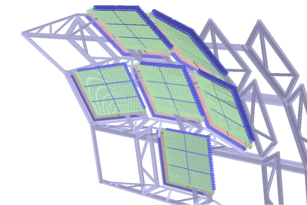
- Visual checking
- Checking overlaps
- See for yourself (New!)
- See for yourself (New!)
- Overlap of the day NONE...
- Overlaps current status 26/01/2009 - ALICE geometry is overlap free within 1 micron
- Material Budget with AliLego
Documentation 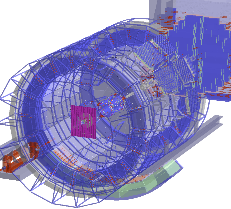
Geometry is represented using ROOT geometry modeller (TGeo). Detailed documentation related to its usage and most of the guidelines below can be found at this location. The documentation of the geometry classes is also a very good source of information.
Geometry can built via VMC API described in the class TVirtualMC, but it is highly recommended to use directly TGeo to create geometry structures. A combination of the two methods is possible .
Creating geometry structures with TGeo
The page is intended for the frugal user but is by no means a replacement for the documentation pointed above. Below are given some recommendations for the procedure to follow when designing, implementing and checking new geometry.
Design & implementation guidelines
TGeo uses a hierarchical model for its volume structures in the style of GEANT. In this sense volumes are like folders - they group together other volumes. As you do not want to keep all the files in your computer in one single folder, the same applies to volumes: make deep hierarchies rather than flat structures (saves CPU time during navigation).
Volumes are not-positioned objects. When positioned they become nodes (daughters) of another volume. The same volume can be positioned in different places inside the same mother volume, but also in other volumes. Use a lot replication rather than duplication (saves memory and is less error-prone) .
Volumes can represent real objects, but also may serve just as virtual containers. In any case volumes are delimiting in space the extent of the contained objects that are not allowed to overpass (extrude) the mother shape. Group as much as possible at low geometry levels volumes that stick together no matter the detector installation (will avoid clashes later-on when mis-aligning the detector) .
Keep in mind that the ideal positions of some of your detector volumes will change due to alignment imprecisions. For those volumes that are supposed to "move" inside their container, leave some room according to the estimated errors .
For volumes that stay pinned to their positions by construction make the virtual container - if this is the case - using the best fitting shape (without leaving useless empty spaces).
If making a virtual container is not possible for a structure of volumes use assemblies . Do not abuse assemblies of assemblies (will cost extra tracking time) .
Start creating your geometry starting from the most low-level structures to most complex ones. Always have a valid geometry (having a top volume and closed) when creating new volumes (this will give you immediate access to all TGeo checking tools )
If starting developing a new geometry module, start from a simple ROOT standalone macro rather than directly in AliRoot. It is easy to migrate your code in the framework once checked, will save the compilation time and will fasten the development cycle.
Geometry checking methods 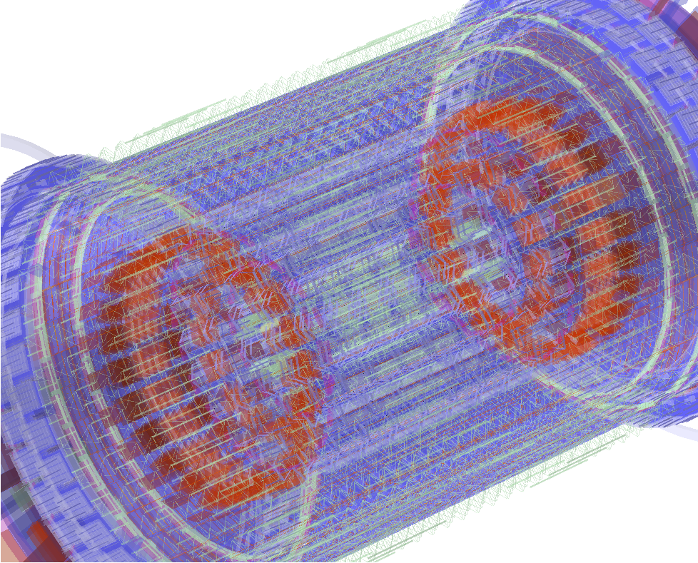
Always check a volume using ALL methods below just after (and even before) assembling all its daughter volumes . Doing this will limit the investigation one level down only. Seems a bit hard to look for problems directly in the structure nearby, doesn't it ?
Visual checking methods
Make sure you have root compiled with OpenGL support. This provides the best quality and interactivity. All methods below can be called from the interpreter or from the context menu of volumes/manager when using a browser. Using the browser is more convenient and recommended.
Visual checking of a single volume for validating its shape. This is not needed for most shapes except TGeoXtru and TGeoCompositeShape for which the validity can not always be checked.
Visual checking of a single volume and its content should be done only one level below . This is the most useful option. To select it use the global settings:
// To see the checked volume also (not just its daughters) do:
root[1] gGeoManager->SetTopVisible();
The problem with having a visible top volume is that it will hide its content in a normal GL view. One can draw in wire-frame mode while in the GL viewer by pressing 'W' - other useful modes ('R' and 'T') - or make the checked volume transparent:
root[1] ptrVolume->SetTransparency(50); // valid range from 0..100
Before drawing the volume, make sure that it is visible, its daughters are visible and better have meaningful colors
root[1] ptrVolume->SetVisibility(kTRUE); ptrDaughter->SetVisibility(kTRUE);
// Daughter volumes are visible by default but may also be hidden (all together)
root[2] ptrVolume->SetVisDaughters(kTRUE);
// By default only terminal volumes in a branch (leaves) or down to the requested visible level will be seen.
// In this case this need to be changed to see also the containers.
root[3] ptrVolume->SetVisContainers(); // Default SetVisLeaves()
// Draw the volume
root[4] ptrVolume->Draw(""); // Use "ogl" for OpenGL view
Visual checking using ray-tracing. This method uses already tracking functionality (navigation and propagation) for the volume structure you are checking. It is VERY important that this produces a picture comparable with the one obtained in the OpenGL viewer as a validation check for a structure. It is recommended that this check is performed also one level down but with different setting:
 |
 |
root[0] gGeoManager->SetTopVisible(kFALSE);
Make sure that you start from a fresh pad (no changes of visibility on the existing pad will take effect otherwise)
Shooting random points or random rays in a volume. These are old but useful utilities. In case of random rays the starting point can be changed from the default (0,0,0). Only the points/rays that are crossing a visible daughter volume will be shown.
 |
 |
root[2] ptrVolume->RandomRays(10000, 0., 0., 0.);
Checking overlaps
In TGeo modeller there are 2 types of illegal overlaps: they are simply called overlaps when two volumes within the same container do overlap each other, and extrusions when a volume overpasses the shape extent of its container. They are both as dangerous and may have unpredictable (but always bad) effects during tracking. The global method for checking overlaps has the prototype:
Here ovlp is the tolerance (by default 100 microns) allowed for the overlapping distance. Note that this value may NOT be appropriate for your detector.
This method can be called for the whole geometry, for a single volume (and daughters) or for a branch (node):
root[0] ptrVolume->CheckOverlaps(args); // Check only a volume and its daughters one level down
root[0] gGeoManager->cd("ALIC_1/TPC_M_1");
root[1] gGeoManager->GetCurrentNode()->CheckOverlaps(args); // Check only TPC branch
Note that only the detected overlaps greater than the ovlp value will be reported. The default value is 0.01 cm but this may not be appropriate for all detectors. The option can be s
The list of overlaps can be retrieved or just printed out:
root[2] gGeoManager->PrintOverlaps();
The default algorithm is just checking the vertices on the mesh of the volume shape against the inside/outside of the neighbours volumes and parent container. The method is the fastest but there are some (but quite few) overlap topologies that are not detected. Extrusions are always detected by this method. The sampling version of the overlap checker is much slower (depends on the number of sampling points per volume) but more accurate. This will NOT detect extrusions nor very small overlaps ( volume size/statistics) so it is complementary to the default method.
NEWS! Starting with ROOT tag 24419 an improvement of the overlap checker was introduced. The option "s" becomes mostly obsolete since the new algorithm detects most overlap topologies.
Overlap of the day
NONE ...
Overlaps can be inspected/visualized using the geometry file overlaps.root
root[1] new TBrowser();
Click Geometry/Illegal overlaps item, choose Details list view type, then double-click some overlap item. Choose View/View with/OpenGL from the canvas.
Overlaps current status
Default overlap checking method improved (root TRUNK). Use:
gGeoManager->CheckOverlaps(0.0001); // 1 micron
0 overlaps > 1 μm (with increased number of mesh points)